
How to Deal With Requirements in Flawed Projects
Some examples of what can go wrong with requirements management in large, distributed projects and how to fix this

Igor Tunjic
2.8.2020
Some examples of what can go wrong with requirements management in large, distributed projects and how to fix this
Introduction
If you take a book dealing with requirements management, you will usually be told how to do requirements management in a simple project starting from scratch.
What you will not find that often is a description of how to behave if you join a project which is already ongoing and which already faces some challenges. The goal of this blog post is to give you some ideas of what can be done to deal with requirements in flawed projects.
What I would like to do is to describe the settings and challenges that our team encountered during a real project. My goal is to give you an impression of which concrete steps we have taken in order to improve the situation and how well the improvement measures worked within the project setting.
Phase A of The Project
Technical Part
Our team had the task to develop a Back End IT solution for monitoring of hours of the service records for truck drivers. Our customer already had an On-Board device solution that recorded the driver’s daily driving and on-duty hours of service (hos) and informed the user if he is compliant with the legislation. The task our team had to fulfill is to develop the Back End of the system and to integrate it with the already existing and productive onboard solution. The central system had to fulfill the following requirements:
- Synchronizing driver’s hos which might be transferred over the air (OTA) or via USB with data already stored in the database. The main challenge here was that system was zero-tolerant regarding mistakes i.e. driver’s hours of service can be thought of as a chain of data with each segment of the chain being dependent on its predecessor. Data arriving in the wrong order or missing data inevitably lead to wrong calculation with regard to the driver’s available working time in a time frame. Therefore, data had to be transferred via a reliable transfer protocol and data processing algorithms in the Back End had to be robust.
- Allowing users to see, add, edit or delete hours of service in the system. Therefore, the system had to provide a user-friendly interface that would allow the user to perform these tasks efficiently.
- If a driver is logged in to an onboard device system central system had to detect if the device’s information regarding the driver’s logs is up to date. If there was information missing on the device’s side the central system had to provide an update of the driver’s log data
- Displaying vehicle tracks on a digital map for a requested time period. Therefore, the system should use GPS coordinates which were recorded by devices and transferred together with hours of service.
Obviously, the task of synchronizing a system of distributed onboard units communicating with the central system via two different channels was not a trivial one.
Organizational Part
The SW installed on devices was built and maintained by a team outside of our project team. Our project team was responsible for the Server-side part of the system. On our side we had two development teams being allocated to different locations outside Germany. Additionally, the project management and the specification team were allocated to different locations in Germany. Communication was done mainly via e-mail. For discussion of daily issues the project scheduled a series of daily meetings which were done via Webex.
Clearly, the synchronization of work between so many distributed teams caused many problems and was a source of more than a few fallbacks within the project.
Challenges
I joined the project 6 months after development was started. I was assigned to the specification and troubleshooting team consisting of 4 members. The situation I encountered was:
- The functionality has been partially implemented – parts of implementation nowhere documented or justified by specification
- Specification of the desired functionality was incomplete. Parts completed were often of poor technical level.
- The specification was kept in word documents. Any change of specification required a time-intensive process of locking the document in the svn, editing the document, asking team members for review and uploading the document again
- Due to incompleteness and poor technical level of specification, the specification was often not used by the development team when writing actual code
- The implemented solution was under permanent testing by our internal test team and by the customer’s test team. Both teams found a huge number of bugs. The root cause for bugs was unclear.
- One of the main issues in the project was the lack of traceability from functional requirements to the implemented solution. All teams involved in the project implementation wished more clarity on the question of how a particular requirement is reflected in the system.
- Nobody in the project seemed to know what is specifically going wrong, yet everybody knows that something is going wrong in the project
Further our had to deal with the following challenges with regard to project management:
- Development teams were from different countries and time zones which made efficient inter-team communication difficult.
- The development followed the waterfall approach where any development step is preceded by an approved functional specification
- Due to a lack of approved specifications, development teams were somehow unclear what exactly to implement. In this case in order not to waste time they implemented something they believe fitted best with customer’s expectation
- Communication, in order to synchronize the development efforts between different teams and to assure that interfaces, data structures, etc. are aligned, was challenging
So, the goal specification team defined was the following:
Establish a requirements management process that will satisfy the following:
- Enable the development and test team to actually develop the SW following your specification
- Enable the specification team to react quickly to changes to desired functionality that might occur in the project
- Improve the overall quality of the specification
- Provide a clear and functionally correct specification of complex requirements
- Make the specification easily usable to every member of the project team
- Allow customers to review and approve the system’s design and functionality in an efficient way
- Include customer’s wishes, additions and corrections into the specification
Improvements in Phase A of Project
Select an Appropriate Tool For Specification
In order to satisfy the requests mentioned above specification team recognized that we would need a tool that will support us in this task. Using a simple collection of documents in .doc format would not do the job.
How would a suitable tool look like from the specification’s team point of view?
- It would allow us to create, group and classify requirements easily.
- It would support UML modeling for the description of complex use cases (e.g. by using activity diagrams)
- It would allow to trace the requirement’s realization in the system starting from the requirement’s definition itself and tracking its implementation all the way down to the components used and database schemata involved (if necessary).
- It would allow splitting work over different areas of responsibility e.g. if the system can be split into different (logical) modules – we would expect different team members to be able to do specification work on each module independently.
- It would allow setting baselines and priorities
- It would come up with a solution for version control.
- And last but not least: the tool would allow you to customize and generate a pdf or .doc requirements document automatically if your customer wants to have it.
Traceability as Key Requirement For Successful Specification
As defined above – one of our key goals was to establish traceability from functional requirements to their implementation on the system level. For this purpose, before starting modeling in our chosen tool we defined a so-called model of the model (Metamodel) of how we would like our specification to be structured in an ideal case:
This Metamodel shows some of the goals we were trying to achieve with our approach:

- For every business, case identify at least one Use case which would represent this feature in the system
- By defining the Use case for the business functionality derive a set of functional requirements at the top level. Call them Level 1 requirements.
- At the same time already start to define the constraints or non-functional requirements your product should fulfill
- Every functional requirement shall be justified by a business cased and realized by a use case
- In order to specify a use case in a detailed way use any UML or non-UML model which might seem appropriate. Possible ways of specifying the functionality of a use case might be activity diagrams, sequence diagrams but also a simple plain text description
- Define a logical data model that describes business objects to be used in future system
- Use the classes defined in the logical data model in order to specify the use case behavior in a detailed way. For example, it might be useful to reference the data objects within an activity diagram in order to explain which data are processed within the activity
- During the detailed definition of use, the case identify L2 (level 2) requirements which describe L1 requirements in a more detailed way
- Define logical system units that decompose your system functionality in a logical way
- Assign the system components to logical system units
- Assign every use case to the logical system unit
After considering all these expectations we decided to opt for the usage of Sparx Enterprise Architect.
Very Short Description of Sparx Enterprise Architect:
- The core of the EA is the model. The model means objects and relationships between them. Often a model or its parts are visualized via diagrams
- Objects in EA might be requirements, use cases, classes, etc
- Associations between objects are stored within the EA database. They are part of the model and do not depend on a particular diagram
- Associations can be constructed and visualized via a model diagram (e.g. associations between classes in a UML class diagram or a diagram showing links between requirements and realizing UCs)
- Packages are used to structure the model
- EA supports the user with the toolset which is already adapted to the desired modeling technique e.g. class elements and association if the user wants to create a class diagram
Experiences With EA
Positive
- Using the package structure in EA we were able to create a structured and complete view on the specification which to that point was spread over different documents. The package structure with Use Cases and Reqs open can be seen in the picture underneath
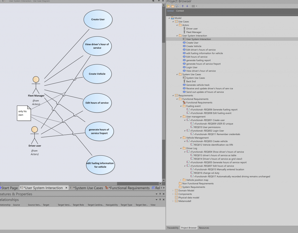
- Modeling within EA enabled the team to better understand complex dependencies between data objects and business rules. By defining the domain model via the UML class model, we were able to show interdependencies between different business data objects, which have not been clearly identified before.
- By using the UML activity diagrams, we were able to model some of the most complex use cases, which have been described in plain language before, the written description being very complex and ambiguous. By using data objects in the activity diagrams, we were able to show which business objects were used in which use case and in which particular step of the use case. Data objects used in the activity diagrams referenced the business objects defined in the domain model. By doing so we were able not only to provide a visual representation of a complex use case but also to connect the domain model with the use cases (traceability).

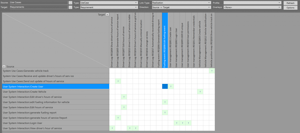
- Linking requirements and use cases via a “realization” connector allowed us to track the requirement’s realization. We were able to identify requirements that were obviously not covered by any of the defined use cases and therefore had no clear implementation trace. Connecting requirements and use cases is an easy task in EA either by using a diagram or a relationship matrix. The picture underneath shows how a relationship matrix in EA can be used to check if all requirements are realized by at least one Use Case.
- The package structure of EA allowed us to structure the areas of work in an easy way. This made it possible to allocate the available resources to particular tasks more efficiently.
- Versioning the EA packages via svn enabled the team to work on different packages at the same time without causing conflicts
Negative
- Modeling in UML turned out to be “expert” knowledge within the project team. Both test teams – the one on our side and the one on customers – found it difficult to derive test cases from UML-based descriptions of Use Cases (often done via activity diagrams). Both teams declared that they preferred a more informal but easier read description of a Use Case via plain text.
- Modeling in EA requires a high level of modeling discipline in order to be useful. The information has to be stored in a predefined manner. Usually, it is the Team lead who defines where a particular set of information is to be stored and who describes this in the modeling rule set. Deviations from the predefined modeling rules result in information being stored somewhere in the model. Anybody using the model will have a hard time finding and extracting the information.
- The development and test team did not want to use EA in order to store their artifacts as they found the EA not suitable for their management. Test cases and implementation orders were stored in a different system. Therefore, full traceability was not established.
- The majority of the team had no experience in using EA and did not want to spare a significant portion of their project time in learning how to use the tool.
Phase B of The Project
A change in official regulation regarding the recording of driver’s hours of service meant that our project had to adapt the already delivered system functionality in order to be compliant with the regulation. As almost all parts of the project were affected by the change this was also a chance to repair some things that did not well in the initial implementation. However, the budget constraints did not allow to do a completely new implementation. Instead, a mixed approach was chosen to mean that our project would keep as much legacy code as possible and would reimplement only what was absolutely necessary. New implementation would be done for those parts which were not delivered yet or for those parts which had to be adapted due to new regulations. From the perspective of the specification team, however, the new approach meant that we would have to more or less rewrite the specification from the scratch. With this, we also received the opportunity to try the new approach for writing specifications based on a modern requirements management tool.
Polarion Instead of Enterprise Architect
Although EA has proven to be very useful when gathering requirements and modeling solutions in a structured way, it quickly became clear that it could not be the main tool used across the project due to lack of acceptance by development and test teams particularly. On the other hand, the architecture team kept using EA for modeling data structures and automatic code generation.
What would be the solution which would allow the development and test team to collaborate with the specification team in the most efficient way?
In order to find the best solution for the project, the specification team interviewed the development and test team about their expectations on the future specification of the system. Following were the requirements of the two teams regarding the specification:
- The functionality shall be specified in a user-story form written in plain English rather than using UML and activity diagrams as both teams tend to understand requirements written in plain English better than descriptions via UML diagrams.
- Use cases shall contain a description of the basic scenario, actors, alternate paths and error scenarios with error messages shown by the system.
- Activity Diagrams shall be used only in exceptional cases e.g. if the basic scenario is too complex to be described in plain text. However, even such use cases shall have in addition to the diagram at least some explanation about the user story written in plain English in order to avoid misunderstandings resulting from the diagram.
- The front end of the system – used by the user to interact with the system shall be described and visualized. Therefore, the specification team shall define a special class of items called GUI elements. Any data shown or edited by the user via interface shall be defined with regard to the allowed character set, length and other constraints. Further, it shall be clear how the data entered, edited or deleted via the front end reflect data stored in the database of the system in the Back End.
- Complex rules, algorithms and so on shall be kept and separate requirements and shall be referenced in the user stories where they might be important for a deeper understanding of the system’s functionality
- GUI elements defined by the spec team shall be referenced in the user stories where this might seem appropriate for a better understanding of desired functionality.
- The development team shall have the possibility to link the implementation orders and test cases to the user story they are supposed to implement or test. The user stories shall be easily maintainable in terms of versioning, release management and status
Additionally, during a lessons-learned session, the project team recognized the shortcomings of the current project’s approach to keeping specification and test items in different systems without links between them.
Therefore an additional requirement was included in the list of features a new tool should possess:
- All defects discovered either during internal tests or on the customer's side shall be stored together with use cases, implementation orders and test cases allowing each user of the system to easily see to which functionality a defect is referring to.
- As the customer’s approval is required for the start of implementation of any of the specified functionality the customer shall be granted a possibility to see, comment and approve or disapprove specification items in the most efficient way. Therefore, the preferred solution instead of sending in an official specification document would be to enable customers to work in the same system as the project team.
In order to satisfy these demands, we decided to take a step back from our originally proposed EA approach and to look for a tool that would satisfy most of the requests posed by the development and test team. The tool which seemed to fit best was Polarion System’s Polarion requirements management tool.
Short Description of Polarion
Polarion is designed primarily as a tool for requirements management and application life cycle management. It supports the user in the creation and editing of different artifacts like Use Cases, Requirements or Test Cases. The editing of artifacts is done in textual form via a word-like editor. This makes it very easy to use also for inexperienced users. Another key feature of Polarion is the possibility to link different artifacts via predefined relations e.g. Requirements and associated Test Cases might be linked via “verify” association. This feature combined with various filtering features in Polarion allows for quick and easy monitoring of traceability in the project. Further Polarion offers a history function for every artifact defined, which for example may be very useful in order to understand a change history of a requirement in a project.
Project Life Cycle Management Via Polarion
The following picture shows a meta-model of specification and the most important development and testing items used by the project in Polarion:

As can be seen from the model our goal was to use one single platform for coordination of the system’s functional description and their coverage and completeness regarding implementation and testing performed by the development teams. In the following, I would like to give a short overview of the artifacts which were used by the specification team in order to describe the system’s requested functionality.
Specification Artefacts
For specification of the system’s functionality specification team defined and used three distinguished classes of objects in Polarion:
- Use Cases
- Requirements
- GUI elements
Use Cases
Use Cases were the core element of the specification.
We defined the Use Cases in Polarion using the Use Case template. This template contained the standard elements needed to describe the majority of use cases sufficiently well for the development and test team:
- Pre- and Post-Condition
- Roles and Permissions
- Basic Path
- Alternate scenarios
- Error scenarios
Additionally, in rare cases where a text-based description was not sufficient, we included activity diagrams modeled in EA.
Requirements
Requirements were grouped into two main classes:
- Customer requirements storing customer’s expectations and requirements to the system as defined in the statement of work agreed between us and the customer. These were used to monitor the system’s progress with regard to the completeness of the contract signed between our customer and his. Each customer requirement was linked to at least one Use Case in order to monitor the progress of the implementation.
- System or internal requirements: Requirements defined by the specification and development team in order to implement the system properly. Often these requirements were used in order to define complex processing routines or data manipulation rules which had to be respected in a particular used case scenario. Each of these requirements was connected with at least one Use Case (for justification of requirement’s definition). In order to make the specification easier to use the system requirements were directly linked in the scenarios in the Use Case where they might play a role. E.g. if in the scenario there was a step that would say: “System includes data object X into structure Y” a requirement would follow as a link where rules and constraints of including data into the system would be explained in a detailed way.
GUI Elements
GUI elements were introduced in order to provide the team a better idea of the expected functionality of the system. GUI depictions were initially drawn in a tool called Wireframe Scratcher. After the drawing was done a png export of the wireframe was be included into a GUI object in Polarion. Same as for system requirements the GUI element was linked to at least one Use Case and was used within the step-by-step scenario description of the Use Case.
One of the main benefits of the GUI specification was the possibility to link the data entered or edited by the user via the system’s Front End to the data stored and processed in the Back End of the system. This was done by specifying the data (via type, range, allowed character set, max and min values) in the GUI element in Polarion. Once the data were described they were linked to the data model stored in the Enterprise Architect allowing architects and system developers to trace the data from the GUI to the system’s Back End.
Particularly the test team found that this approach improved the quality of the test cases
Maintenance of Specification Artefacts Using Tags
For each of the artifacts used for the specification, we used a set of tags to track the status of the object with regard to its completeness, its role in the big picture of the project and its status of approval. The most important tags used were:
- Priority to describe the item’s priority with regard to the overall functionality of the product. This was important in order to understand which functionality was a “must-have” and which was a “nice to have” within the current development cycle.
- Complexity to describe the estimated amount of work required for development and testing
- Planned/delivered release to describe in which release the functionality described in the object was supposed to be delivered and when it was finally delivered. This one was particularly important in order to communicate to the customer the content of a particular release, which one his side was essential for preparing to test of the delivery. On the other side, it was absolutely essential for the project team in order to keep track of which functionality was already implemented and delivered.
- Status describing the status of the item with regard to specification (in process, finished, approved)
- Module describing to which logical part of the product the item ways belonging to (e.g. HOS module or Vehicle Tracks module). This classification was particularly important for the efficient assignment of working packages to development teams
Polarion Acceptance Within Project Team
Polarion was widely accepted within the project team. Following Polarion features were mainly responsible for it
- It is easy to filter and order items by attributes e.g. their priority, category and complexity. This allows all users to easily create a view of the project items which suit best for their task within the project. It also allows the moderator to change and adapt views quickly during a discussion with the team.
- It is easy to edit and read items. There is no expert knowledge needed in order to create or understand a plain text description of a Use Case or a Test Case in Polarion.
- It is easy to grant read and write permissions to a user for a subset of Polarion items. E.g. This allowed us to provide the customer with access to our specifications and to enable him to directly participate in specification work by approving items or commenting on them in case there was something unclear from his point of view. This made the discussion with the external customer much easier.
- It is easy to define categories for Polarion items. Therefore, it is easy to structure the project
- Recalling historical versions of a Polarion item is easy. Changes between two versions are highlighted and it is tracked who did which change. This turned out to be a very useful feature when discussing disputed points with a customer.
Supporting Transformation From Waterfall to Agile Approach
During the implementation of Phase B, it turned out that the overall performance of the project team was not satisfying the customer’s expectations. Neither the speed of delivery nor the quality of the delivered functionality was as desired. Following shortcomings were identified as main reasons for this:
- The decision to keep big parts of legacy code in the system in order to save development time. This decision meant that developers encountered the problem of maintaining code they were not familiar with. Like in many other SW projects the development team changes over time with people leaving the project and taking their specific knowledge with them. Maintaining old parts of code and integrating new parts of code with legacy code was expensive in terms of the developer’s time. This resulted in reduced performance with regard to the delivery of the new features.
- Many bugs could be detected only when the product was put into production with real-world users. This resulted in a significant number of critical defects that had to be fixed after the delivery of the product into production. Fixing bugs in an already mature stage of a project was very costly in terms of effort.
- The development team had to deliver the productive system very quickly due to a fixed release date set by the marketing department. This resulted in the system being developed under a rush without paying too much attention to clear structures, modularization, and clean code. Therefore bug tracking and bug resolution were a challenge as many parts of code had interdependencies that were not obvious.
- Business requirements were changing during the project depending on the feedback provided by product users. This led to the request for a significant number of new features to be implemented in the system. The effort estimations for these tasks were often disputed by the customer and resulted in very intense and time-consuming discussions.
- Integration of our part of the system with the distributed part of the system (onboard devices) turned out to be quite challenging. On several occasions, the BE system had to be adapted due to bugs on the side of the device. Any change to the parts of the system which were interacting with the devices in the vehicles had to be tested thoroughly before being put into production. Tests were very costly in terms of resources. However, it was not always easy to explain to the customer why certain tests were so cost-intensive.
Agile Approach
As a reaction to these problems, project management took the decision to change to an agile approach with regard to development. The decision was taken to follow the SCRUM framework with its typical structure of sprints, sprint teams, sprint backlogs, etc…
Improvement Expectations
By introducing SCRUM the project management sought to achieve the following improvements:
- Deliver runnable system increments faster in order to enable the customer to evaluate the system quicker and to provide his feedback faster
- Increase team cohesion by building scrum teams and making everybody in the team feeling responsible for the delivery
- Make team more flexible with regard to changes in business requirements which make code changes necessary
- Minimize efficiency loss resulting from sudden changes of priorities in the project. In the past, we very often encountered a situation where development for a product functionality had to be interrupted due to a critical issue for which the customer insisted that it had to be fixed immediately. Interruption always meant the loss of working time due to the effort necessary for the reorganization of the work. By forcing customers to respect the fixed sprint structure we hoped to minimize the number of situations where unfinished work had to be interrupted in order to do something more important from the customer’s point of view.
Clearly, changing to SCRUM meant a significant adaptation with regard to the project structure. Particularly we had to map the current roles in the project to the roles expected by the SCRUM framework.
Transforming The Structure of The Team
At the beginning of the second phase, our team structure still reflected the old waterfall approach. The team consisted of:
- Project Manager
- Development lead also being project manager’s replacement
- Specification team consisting of 5 members
- The architect for Back End functionality
- The architect for Front End functionality
- 2 development teams each 5-9 members strong. Two teams were not in the same town
- 2 separate test teams supporting the work of the development team
The challenge was to transform this rather inflexible structure to SCRUM roles.
Roles:
Typically, a project following SCRUM has to define 3 roles: Development Team(s), Product Owner and SCRUM Master. The following table shows how the project structure was mapped to SCRUM roles.

Development Team
The obvious approach was to declare the already collaborating development teams and test teams to a SCRUM development team.
The specification team provided support to the development team but was not a part of the development team. For example, specification team members did not take part in daily scrums.
SCRUM Master
In the SCRUM framework, a SCRUM master is a person who is responsible for the moderation of the SCRUM principle within the project. This person is supposed to be a moderator who is responsible for introducing the SCRUM within the project. This means he is responsible for the explanation of how SCRUM actually works, explaining to everybody his role in the team to pay attention that SCRUM rules are respected with regards to daily scrum meetings, scrum retrospectives, etc. Also, it is the SCRUM master who is responsible to challenge any obstacles which might prevent the development team from performing its work.
This part was taken over by the project manager(s), and the development team itself.
However, nobody was appointed to the task of teaching and establishing the SCRUM approach. This task was performed by the development team on its own.
Product Owner
In SCRUM Product Owner has the task to be the connection between external stakeholders and the development team. His most important tasks are:
- Creation of a product backlog
- Participating in definition of sprint backlogs
- Clarification of expectations regarding functionality towards the development team
- Keeping track of priorities of items in the product backlog
- Providing a definition of done for a sprint
Our previous team structure and the complexity of the project did not allow one single person to take over all these tasks. Instead, each of these tasks was taken over by one or some previous team structures. E.g. communication with external stakeholders in terms of desired functionality and prioritization of product backlog items was taken over by the specification team and project manager respectively.
Challenge For Specification Team When Implementing The SCRUM Framework
The specification team had to adapt its work to the SCRUM approach of the development team. On the other side customer still insisted on formally approving any functionality prior to its implementation. This resulted in a somehow contradictory situation of a project following a “waterfall” approach towards the outside world and agile (using SCRUM) on the inside.
Following challenges were encountered by the specification team when changing to the SCRUM approach:
- The specification artifacts consisting of Use Cases, functional and system requirements and wireframe elements connected with an underlying data model do not fit into the typical User-Story based requirements communication used by SCRUM. Therefore, the specification team had to support the development and test team in order to find the best way to include these items in the product and sprint backlog.
- The customer insisted on the formal approval of any functionality prior to its implementation. Receiving formal approval was time-costly due to a lack of resources. On the other hand, project management insisted that as much functionality as possible shall be delivered as quickly as possible
- Prioritize functionality items and discovered bugs in order to decide what to include in the next sprint
- Assure that the effort estimations for new features or bug fixing are done
- Discuss already approved features with customers again in case that during a sprint implementation turned out to be too complex and try to find a way to resolve it.
How to Define a Sprint Backlog in a Foggy Project
A key part of SCRUM is the sprint and its sprint backlog. The sprint backlog is a subset of items from the product backlog which is promised to be delivered at the end of the sprint.
The product backlog in our project had three sources to be filled from:
- Functionality originally agreed in a contract and specified by the specification team
- Bugs and defects either reported by the customer or by our test team
- Functionality requested by the customer, which was not part of the original contract but turned out to be important for business case
As stated above in order to be allowed to become a part of the sprint backlog a functionality from the product backlog had to specify and approved by the customer:
The approval process looked like the following:
- The specification team tags the items for approval as finished and waiting for approval
- A list containing a query for Polarion search would be sent to the customer
- After a review phase, the customer would either approve the items or disapprove them. In case of disapproval, the customer was obliged to add comments to the disapproved item with reasons and open questions which lead to disapproval
- Disapproved items would be discussed in a meeting between the customer and specification team in order to find a solution for open questions
Note: All these steps could be performed efficiently only because Polarion allowed us to grant our customer access to a distinguished part of our specification. This was done by giving him rights to read and edit Use Cases, Requirements and GUI elements. On other hand, customers had no permission to see the linked test cases or internal issues linked to these objects. If we had had to use the old approach of providing the customer a word-documentation and maybe an excel table with the list of features for his approval – this would have resulted in much longer approval periods.
In order to create a sprint backlog, we had to take into concern priority and effort estimation of items in the product backlog.
Effort estimation was done by the development team under the surveillance of the specification team.
According to SCRUM development team should use around 10% of its time for the estimation of items in the Product backlog. In our project, this was not acceptable. Instead of blocking the complete development team with estimation poker for backlog items, we followed another approach. In our project, it was the specification team that was responsible to request and gather the estimations for backlog items. We used the following approach to get the estimations from the development team
- Identify the member of the development team who knows best about the requested functionality (usually this person was proposed by the development team lead)
- Identify the member of the development team who knows best about testing needed for this functionality
- Get the effort estimations for development and testing
- Compare to the effort spent on some similar functionality if such exists in the system
- In case there are significant doubts about ask for clarification from the dev team
One of the challenges was how to find a good trade-off between critical bugs and new functionality when defining a sprint backlog. Typically, a bug affecting a huge number of users would prevail over an already approved functionality and would be implemented instead of new functionality. On the other hand, it was in the project’s main interest to deliver as much new functionality as possible as this one was agreed by a contract and was, therefore, the main criterium by which the team’s productivity would be measured by its own management. Therefore, each sprint backlog definition was accompanied by strong discussions within the project team and between the project team and the customer.
Communication Within The Project
As we were working in distributed teams, we had to find a tool that would allow us to communicate issues, questions, problems and solutions in an inefficient way. We found that the “Slack” chat tool perfectly suited our needs. E.g. it allowed the dev and test team to directly address the specification team in case there were open questions with regard to functionality that had to be implemented. In many cases, gaps or contradictories within the descriptions of desired functionality were addressed by the test or dev team.
Results And Summary
There is no out-of-the-box solution for such a complex task. Instead of trying to find a single tool-oriented solution for all problems you should rather focus on improving all parts of the project in parallel. Of course, using the right tools might have a significant impact on your team’s productivity but not less important are questions of organization, project management, communication and last but not least confidence.
Our team started by introducing Sparx System’s Enterprise Architect modeling environment in order to gain a deeper understanding of the technical side and the issues that we encountered in the project. Over time we almost completely abandoned our EA approach, due to resistance we met within the project team. Instead, we decided to use a less model-based more plaint-text-based specification approach which suited better to the requirements posed by the dev and test team. We evaluated a number of tools and finally selected Polarion Software’s Polarion requirements management tool. Polarion was used to coordinate the work of the specification team and the development/test teams. Change to Polarion was an important contributor to the project’s success.
However, besides moving to modern requirements management tools we also undertook organizational reconstruction. During the project, the development team and test team changed from a waterfall to an agile approach. Both the change in tools used for requirements management proved at least as successful and important as the improved quality of the specification.
Table of Contents
Newsletter
Stay up to date about content and events.
Upcoming EventsEvents overview
Upcoming Events


Events overview


Workshops
Resources
All Rights Reserved.